Structures
A good structural representation has modules, nets and an incidence relationshipbetween modules and nets. We represent structures using incident structures. A simple model for the structure is a hypergraph, where each node represent the module and each edge represents the nets. The relationship between modules and nets could be formally captured via a incidence matrix. The incident matrix is mostly sparse. >A sparse matrix is ==a matrix where most elements are zero==, making it efficient to store and process by only saving non-zero values, thus saving significant memory and computation time, common in fields like data science, graph theory, and machine learning.
An alternative to the above is to have module pins as nodes and nets as edges. Often an incidence matrix is sparse and netlists are an efficient way of description
m1: n1, n2, n3
m2: n1, n2
m3: n2, n3
A netlist can be module oriented or net oriented depending on how you describe it. Incidence structures can be hierarchical in the following ways. A leaf module is a primitive with set of pins and A non leaf module is a set of modules (sub-modules), set of nets and an incidence structure relating the nets and the sub-modules.
Logic Network
A Generalized logic network is a structure, where each leaf module is associated with a combinational or sequential logic function. While this concept is general and powerful, we consider here two restrictions to this model - the combinational logic network and the sequential logic network.
An acyclic graph is a graph (nodes and edges) that contains no cycles or closed loops, meaning you can’t start at a node and follow the edges to return to the same node. While the general term refers to any graph without cycles (a connected one is a tree, disconnected is a forest), it most often refers to a Directed Acyclic Graph (DAG), where edges have a one-way direction, common in scheduling, data flows, and dependencies.
The combinational logic network, called also logic network or Boolean network, is a hierarchical structure where:
- Each leaf module has multiple inputs and one output combinational logic function, called a local function.
- Pins are partitioned into two classes, called input and outputs. Pins that do not belong to submodules are also partitioned into two classes, called primary inputs and primary outputs.
- Each net has a distinguished terminal, called a source, and an orientation from the source to the other terminals. The source of a net can be either a primary input or a primary output of a module at the inferior level. (In particular, it may correspond to the output of a local function.)
- The relation induced by the nets on the modules is a partial order.
The synchronous logic network model is a generalization of the combinational logic network model, to support the description of sequential synchronous circuits. In this model, leaf modules can implement multiple-input single-output combinational logic functions or synchronous delay elements. Nets are not required to induce a partial order on the modules. Nevertheless, the subset of the nets whose source is not a delay element must induce a partial order on the modules to model the requirement that in a synchronous circuit there are no combinational feedback.
State Diagrams
Go through Haris and Haris (Melay and Moore) model # Data-flow and Sequencing Graphs The following structures discussed below are used to model the abstract information represented by procedural HDLs with imperative semantics.
An imperative semantics programming language ==focuses on how to achieve a result through step-by-step commands that change the program’s state (variables, memory) sequentially==, unlike declarative languages that focus on what the result should be.
Abstract models at architecture level are in terms of tasks(or Operations) and their dependencies. Tasks may also be a NOP (no operation) which means the state of the system remains unchanged with no side-effects.
So the question is why does dependencies arise ? 1. Availability of data, there can be data dependencies between two operation so one might have to wait for the previous operation to finish and make the data available. 2. Spec compliance, it can be protocol or anything else that might specify you to skip or wait or make something available before you go ahead example a bus where once data is loaded you are expected to raise a flag. 3. Resource contention and sharing, if the resource or computational block is performing some operation then there are dependencies. Though, that, in general, dependencies due to resource sharing are not part of the original circuit specification, because the way in which resources are exploited is related to the circuit implementation
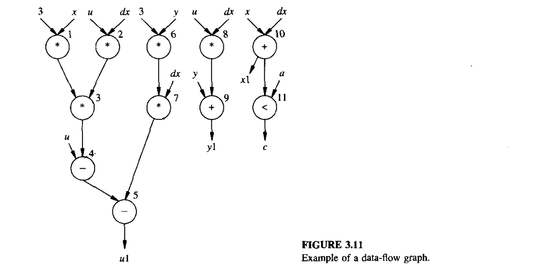
Data Flow Graphs
Data flow graphs represent the operations and their data dependencies.
Let the operation be \(n_{\substack{\text{op}}}\). A data-flow graph \(G_d(V, E)\) is a directed graph who’s vertex set \(V = \{v_i ; i=1, 2, 3, 4....., n_{\substack{\text{op}}}\}\) is in one-to-one correspondence with the set of tasks. The edges \(E = \{(v_i, v_j) ; i,j=1, 2, 3, 4....., n_{\substack{\text{op}}}\}\) show the transfer of result/data from one node/input to the other. Data-flow graphs can be extended by adding other types of dependencies, such as task serialization, that are represented by additional directed edges.
The data-flow graph model implicitly assume the existence of variables whose values store the information. Each variable has lifetime that is the interval form the birth to death.
Control Flow Graph
Control flow information, related to branching (or conditional) and iteration (or loop) constructs, can also be represented graphically. While there are multiple models to do this the simplest model is to simply extend the data-flow graph with branching and conditional nodes. So in case of iteration there is conditional jump or exit out of the branch.
Sequence Graph
A more stable model where we can build intuition and proofs is by using sequential graphs. Sequential graph is a hierarchical control/data flow graph, where the control flow such as branching and iteration is modeled through hierarchy and data-flow and serialization dependencies are modeled by graphs. In addition the model supports model call feature which lets you encapsulate subsets of operations and their dependencies into blocks that can be invoked.
To be more specific \(G_s(V, E)\) is a hierarchy of directed graphs. A generic element in the hierarchy is called a sequencing graph entity. A sequencing graph entity is an extended data-flow-graph that has two kinds of vertices: operation and links, the latter linking other sequencing graph entities in the hierarchy. Sequencing graph entities that are leaves does not have the link vertices.